
Capacitors for water pumps
CBB60 run capacitors and CD60 start capacitors for water-pump motor circuits, with ratings, connection and mounting requirements.
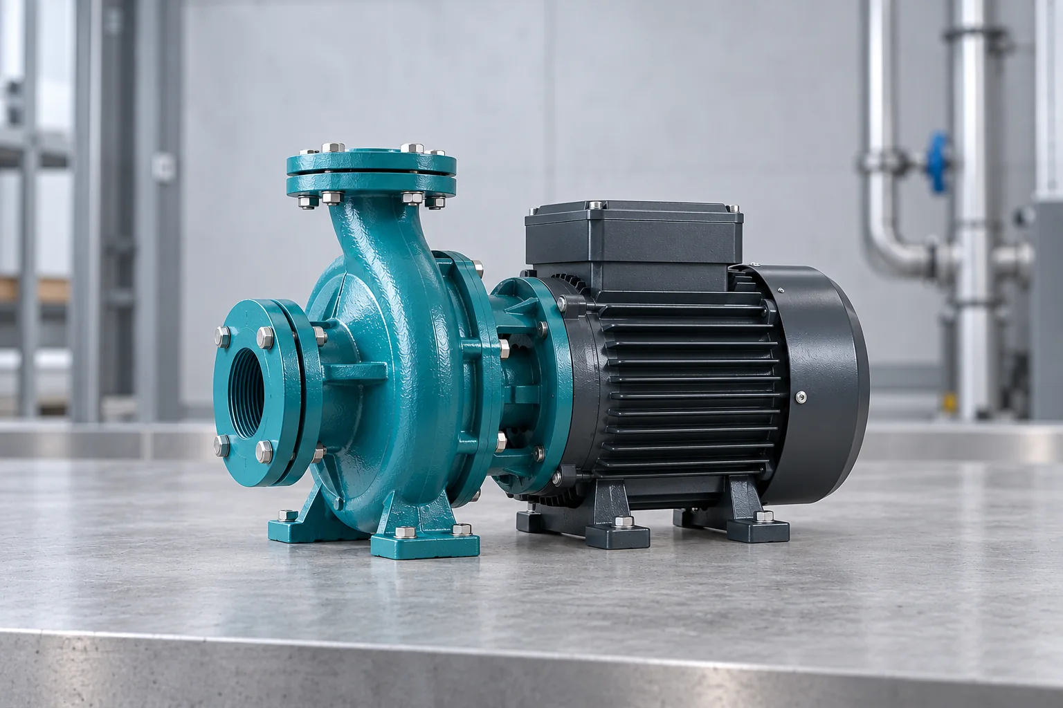
Motor circuit and capacitor requirements
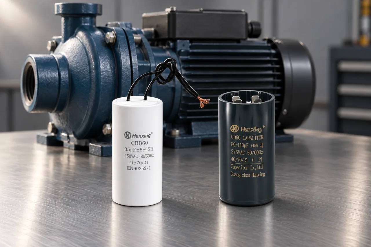
Run
CBB60 run capacitors stay connected while the pump motor runs. Match the capacitor to the motor specification.
Start
Use CD60 in a switched starting circuit. Follow the model’s rated starting time and interval between starts.
Both
If the motor uses both, list each capacitor separately with its µF, VAC, connections and position on the wiring diagram.
Identify the duty
Send the capacitor labels and motor wiring diagram with an inquiry. They identify each part’s rating and circuit role.
Compare capacitor series
| Field | CBB60Run duty · Motor run | CD60Start duty · Motor start |
|---|---|---|
| Duty | Run duty for the pump motor circuit. | Start duty in a circuit that switches the capacitor out after starting. |
| Case / connection | Insulated cylindrical case · Lead wires / quick-connect terminals | Electrolytic start-capacitor case · Blade terminals / wire leads |
| µF / VAC range | 2–100 µF · 110–450 VAC | 20–1500 µF · 110–330 VAC |
| Installation requirement | Cylindrical body, fixing and space for routed leads. | Switching arrangement, maximum on-time and minimum rest interval. |
| Product view | 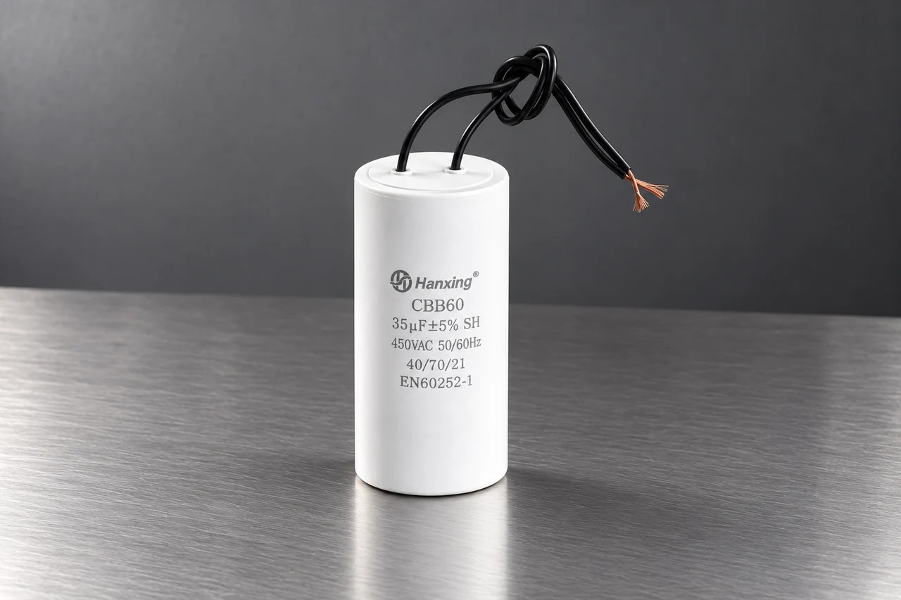 | 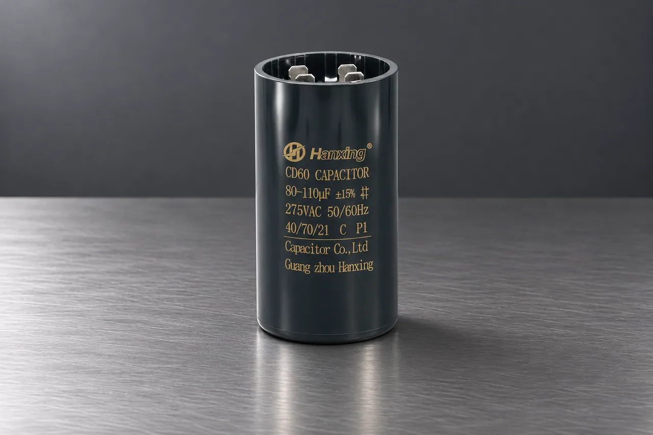 |
| Full series details | View CBB60 | View CD60 |
CBB60
- Duty
- Run duty for the pump motor circuit.
- Case / connection
- Insulated cylindrical case · Lead wires / quick-connect terminals
- µF / VAC range
- 2–100 µF · 110–450 VAC
- Installation requirement
- Cylindrical body, fixing and space for routed leads.
CD60
- Duty
- Start duty in a circuit that switches the capacitor out after starting.
- Case / connection
- Electrolytic start-capacitor case · Blade terminals / wire leads
- µF / VAC range
- 20–1500 µF · 110–330 VAC
- Installation requirement
- Switching arrangement, maximum on-time and minimum rest interval.
The model datasheet provides the applicable temperature, tolerance and dimensional limits.
Mounting and connection requirements
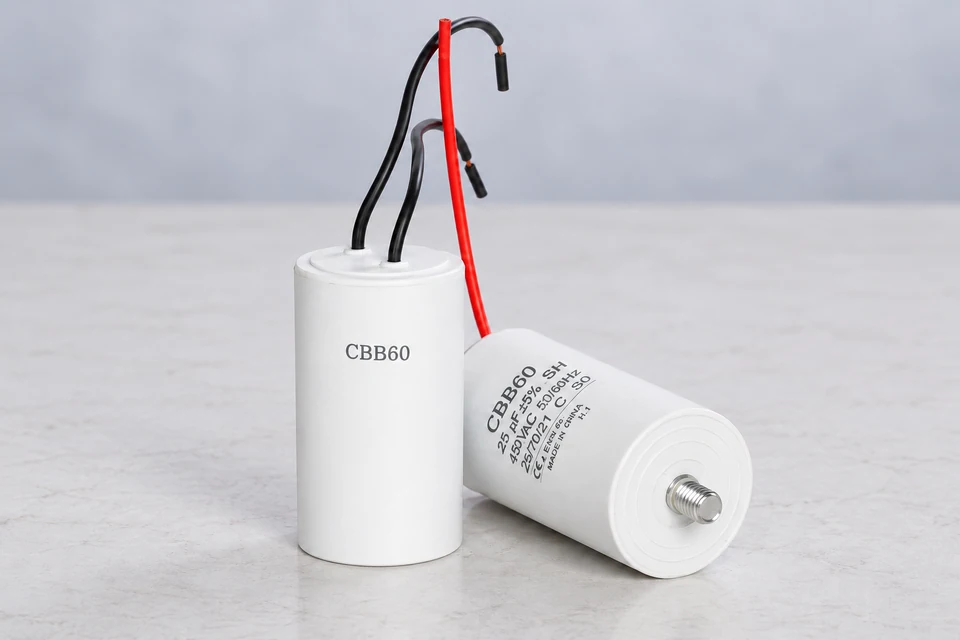
Body and base stud
Measure body diameter, height, stud and fixing dimensions against the proposed model drawing.
Lead clearance
Include the lead exit, length and connector, allowing room to route the leads at the installed location.
Separate parts
A motor with both start and run capacitors needs separate installation and connection details for each part.
Ask about capacitors for water pumps
Send the motor details and the quantity you need.
- Pump and motor model, with the original capacitor label and circuit diagram.
- Drawing or measurements for the installation described above.
- Quantity for each part, destination and any required documents.