
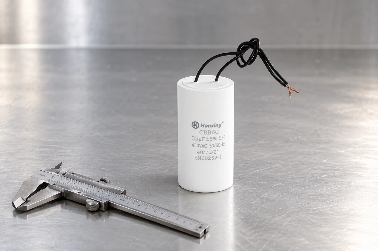
The catalogue gives a 35 µF CBB60 in the 370–450 VAC group a body size of Ø45 × 90 mm. The complete installed height also includes the connections and mounting hardware. Use the table to shortlist a case, then use the selected model drawing for the assembly.
Case diameter and height by rating
Each cell below is diameter × body height in millimetres, transcribed from printed page 7 of the Zebang Refrigeration catalogue. The voltage groups overlap. A quote should identify the actual model and the column used, so two suppliers are comparing the same construction.
| µF | 110–300 VAC | 250–400 VAC | 370–450 VAC |
|---|---|---|---|
| 2 | 30 × 60 | 30 × 60 | 30 × 60 |
| 5 | 30 × 60 | 30 × 60 | 30 × 60 |
| 10 | 30 × 60 | 30 × 60 | 34 × 60 |
| 15 | 30 × 60 | 34 × 60 | 34 × 70 |
| 20 | 34 × 60 | 36 × 70 | 40 × 70 |
| 25 | 36 × 70 | 40 × 70 | 45 × 70 |
| 30 | 40 × 70 | 45 × 70 | 45 × 80 |
| 35 | 40 × 70 | 45 × 70 | 45 × 90 |
| 40 | 45 × 70 | 45 × 80 | 45 × 100 |
| 45 | 45 × 70 | 50 × 90 | 50 × 100 |
| 50 | 45 × 70 | 50 × 90 | 50 × 100 |
| 60 | 45 × 90 | 50 × 90 | 50 × 110 |
| 70 | 50 × 90 | 50 × 100 | 50 × 125 |
| 80 | 50 × 90 | 50 × 100 | 50 × 125 |
| 90 | 50 × 100 | 55 × 100 | 55 × 125 |
| 100 | 50 × 125 | 55 × 125 | 60 × 125 |
Why a 35 µF 450 VAC part needs more than 90 mm
The 90 mm catalogue dimension is the case height. A fitted blade connector projects above the terminal end; wire leads need a route that avoids pinching beneath the cover. A base stud extends below the case. Adding these features to a 90 mm body can exceed a compartment that appears adequate from the catalogue alone.
For an existing pump bracket, record its usable internal diameter and maximum installed height. The model drawing adds the body tolerances, stud thread and usable length. Dimensions for unlisted ratings must come from their own model drawings.
Allow room to connect and fasten the part
A wired capacitor needs a defined lead length, connector and exit direction. For quick-connect terminals, blade width, thickness and spacing belong on the drawing along with the clearance for inserting the mating connector. Twin-core cable and separate leads can occupy different paths even when the capacitor body is identical.
The P003 photograph also includes a separate D&L-marked part. The horizontal 25 µF sample is the reference used here; the photograph does not establish the other part’s full specification or availability.
Fit the sample with its fixing tightened, connector seated and harness routed as intended, then close the equipment cover. Keep that arrangement with the approved drawing revision so the production order reproduces the same fit.
CBB60 threaded base stud and lead exit
Use the model drawing to measure the stud and connected height.
Get the drawing for the selected case
Include the µF, VAC, maximum installed size and fixing method with your drawing request.