
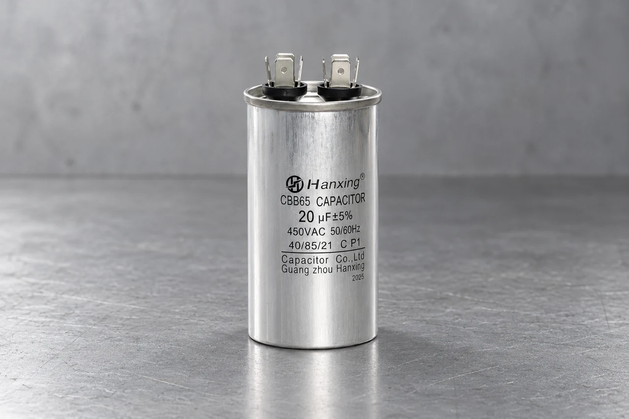
Compare an out-of-circuit capacitance measurement with the part’s nominal value and tolerance under the specified test conditions. For 20 µF ±5%, the calculated limits are 19–21 µF. A reading near a limit also needs the meter’s accuracy and the agreed acceptance rule.
Measure with the equipment isolated
This work belongs to a qualified technician. Isolate the equipment, prevent re-energization and follow its approved discharge procedure. Verify the absence of hazardous voltage with a suitable instrument before disconnecting the capacitor for measurement. Stored charge can remain after the supply is removed.
Use capacitance mode on a meter with a suitable range and known accuracy. Measuring the isolated component avoids parallel circuit paths affecting the reading. Follow the meter instructions for lead compensation, settling time and any connection requirements. An LCR meter used for acceptance testing also needs the specified test frequency and signal conditions. Fluke: measuring capacitance
Calculate the band from the nominal value
Multiply the nominal capacitance by the tolerance percentage to obtain the allowed deviation. Subtract and add that deviation for the lower and upper limits. The examples below are calculations from nominal labels; they are not measured sample or batch results.
| Nominal | Lower limit | Upper limit |
|---|---|---|
| 4.5 µF | 4.275 µF | 4.725 µF |
| 20 µF | 19 µF | 21 µF |
| 25 µF | 23.75 µF | 26.25 µF |
| 35 µF | 33.25 µF | 36.75 µF |
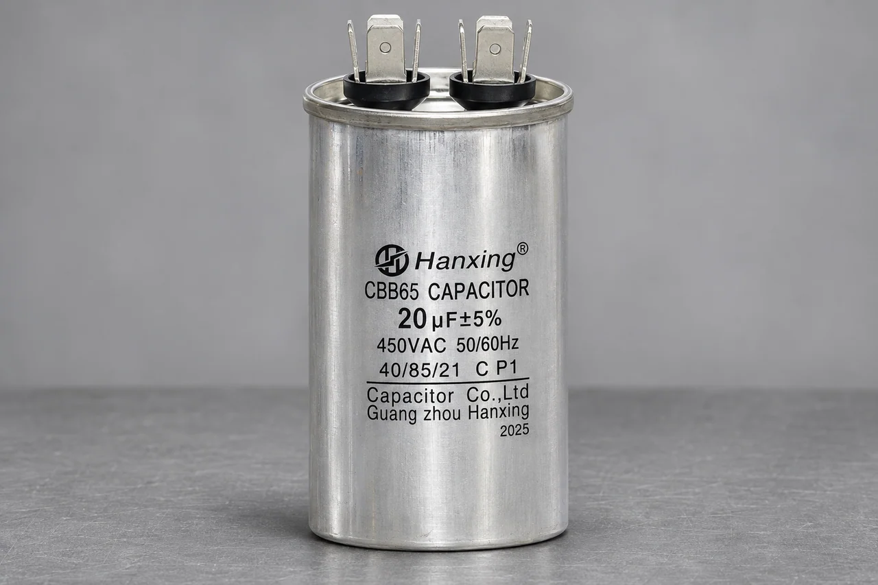
20 µF ±5% on the original label
20 µF ±5% gives calculated limits of 19 and 21 µF.
A borderline display needs an accuracy allowance
Suppose a 20 µF ±5% component displays 19.0 µF. That is the calculated lower boundary, but the display is not an exact value. Meter accuracy, resolution and the agreed measurement uncertainty determine whether the result supports acceptance. Use the inspection decision rule rather than rounding the reading into the permitted band.
OL depends on the meter mode and range. It can indicate an over-range or other condition defined in the instrument manual; it does not by itself prove an open capacitor. A zero or unexpectedly low reading also needs the range, connections and measurement setup resolved before classifying the fault.
Record enough information to reproduce the decision
A useful test record names the model, sample or lot, nominal value, tolerance, measured result, method and date. Add instrument identification, calibration status and test conditions. For a dual-run capacitor, record each section against its assigned terminal pair and its own nominal value.
Capacitance alone does not establish insulation resistance, dielectric strength, dissipation factor or endurance. A damaged case or leaking part also needs removal from service and investigation regardless of one capacitance reading. Additional electrical tests require the correct equipment, model limits and safe procedure.
Define the inspection for your order
Include the model, required tests and acceptance conditions with the report format you need.